Glowing line FX
BlitzMax Forums/BlitzMax Programming/Glowing line FX
| ||
| Hi all, what modules can be used to create some glowing line FX (e.g. as shown on a Vectrex screen)? I have already found indiepath's module that creates some fantastic looking glowing lines but are there any other modules (or codes) out there? indiepath seems to be absent and the module is not documented nor do I have an example. It's a pity since his stuff (there's some screenshot out here of a Thrust remake) looks amazing. Can anyone help? Thank you guys! |
| ||
| what is the theory behind it? i know people use a glowing dot image ,vertices and uv coords but in what way? |
| ||
| Good question! indiepath uses a glowing dot image to draw a line. The line's divided and the dot is repeatedly painted along this (line) path. This looks somewhat pretty cool. But actually I am looking for a more dynamic way to handle the glow FX. The issue with the dot image is that you cannot change its characteristics during runtime (expect for loading different images). |
| ||
| what characteristics would you change? If I understood the theory behind it I could do it. |
| ||
you can use open gl, which I dont know how to use, anyway just make the uv coords like this for a glowing dot image texture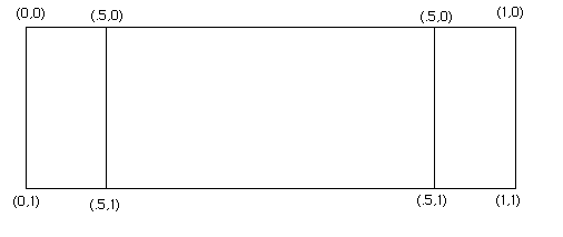 |
| ||
| You have the basic idea. I'm not sure what you want to modify about it dynamically? |
| ||
| @Nate: just doing the coord. won't make any FX. It's more like combining several stuff to achieve the desired glowing. indiepath uses stuff like AlphaBlending which at this point of time I have absolutely no clue about. Think I will try to understand what indiepath is doing. If I suceed I will post the basics here. @Imaginary: if one uses a static image like a glowing dot the effect will always loook the same (except for changing blending etc.). You can not change the 'fadeout' of the glowing since it's fixed in the image (let's call this density; the dot has max. density in its middle fading out to the border). I think about an effect that's basically like a fog surrounding the line (or whatever). This 'fog' is rendered dynamically and you can change things like density and fading since it does use a fixed image as blueprint. |
| ||
| Thanks to Nate the Great I've been playing about with point sprites again :D Here's the result, bresenhams line algorithm + pintsprites + lightblend it doesnt take into account how many points are needed for it to look ok. You have to tweak blocksiz. A blocksiz of 1.0 would be 1 pixel on the screen.  |
| ||
| I really like this. The only thing that bothers me is the lines that are almost straight. They appear jaggy. [edit] nm, I found out about the block size parameter. Looks cool. Would look even better with some custom line images!! I don't understand one bit of the block scan algorithm though =] What's it for? !warning: I am working on a new line object engine atm, so your code might be used in that if you're OK with it. I currently use indiepath's module again, but more options=cool. I'm also wondering how this will scale to 1000s of lines. |
| ||
| @TWH: this is cool! It's almost what I was looking for! Thank you very much for sharing! @Wiebo: it's the line algorithm. Change this if you don't feel happy with Bresenham's look (to me it's too 'steppy') e.g Wu's Algor. (http://freespace.virgin.net/hugo.elias/graphics/x_wuline.htm). |
| ||
Function glLine( x1:Int,y1:Int, x2:Int,y2:Int, gl_image:Int, size:Int = 5 )

	Local angle:Int = ATan2( y2-y1,x2-x1 )

	glEnable GL_TEXTURE_2D
	glBindTexture GL_TEXTURE_2D, image

	glBegin GL_QUADS
		glTexCoord2d( 0,0 )
		glVertex2i x1+Cos(angle+225)*size, y1+Sin(angle+225)*size
		glTexCoord2d( 1,0 )
		glVertex2i x1+Cos(angle+135)*size, y1+Sin(angle+135)*size
		glTexCoord2d( 1,0.5 )
		glVertex2i x1+Cos(angle+45)*size, y1+Sin(angle+45)*size
		glTexCoord2d( 0,0.5 )
		glVertex2i x1+Cos(angle+315)*size, y1+Sin(angle+315)*size

		glTexCoord2d( 1,0.5 )
		glVertex2i x1+Cos(angle+45)*size, y1+Sin(angle+45)*size
		glTexCoord2d( 0,0.5 )
		glVertex2i x1+Cos(angle+315)*size, y1+Sin(angle+315)*size
		glTexCoord2d( 0,0.5 )
		glVertex2i x2+Cos(angle+225)*size, y2+Sin(angle+225)*size
		glTexCoord2d( 1,0.5 )
		glVertex2i x2+Cos(angle+135)*size, y2+Sin(angle+135)*size

		glTexCoord2d( 0.5,0 )
		glVertex2i x2+Cos(angle+225)*size, y2+Sin(angle+225)*size
		glTexCoord2d( 0.5,1 )
		glVertex2i x2+Cos(angle+135)*size, y2+Sin(angle+135)*size
		glTexCoord2d( 1,1 )
		glVertex2i x2+Cos(angle+45)*size,  y2+Sin(angle+45)*size
		glTexCoord2d( 1,0 )
		glVertex2i x2+Cos(angle+315)*size, y2+Sin(angle+315)*size

	glEnd

EndFunction
It's not optimized at all, but here's a quick implementation of Nate the Greats solution. |
| ||
| I wouldn't use cos / sin in this case. 90 deg angles are trivial with vectors, especially in 2D. Just exchange X and Y component and negate one of the two. If the original "axis vector" was uniform, thats all you need to calc for one side of the axis (all vertices right of middle line for example, achieved through point + 90deg rotated vector). the opposite side is just - 90deg rotated vector |
   |